Archon has performed hundreds of pipe stress analyses for the nuclear power Industry.
Piping systems in a nuclear power plant must be designed to resist normal operating loads as well as seismic loads. Other systems, not required for nuclear safety must be designed so that their failure does not cause damage to safety related lines. These lines and their supports are classified as seismic II/I.
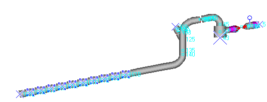
Added Valve Weight Project:
This project was performed for a nuclear power plant. The concern was that added weight applied to a valve by leak seal equipment would cause increased stresses in the line or deflections that would cause damage to the system. The client was considering placing cribbing under the valve as temporary support.
The system was modeled in our DST Pipestress computer program. The additional weight was added to the valve.

Our analysis showed that the general pipe stresses and support loads were acceptable. Deflection was not significant. In order to insure that an equipment nozzle was not overstresses, the resultant loads from the pipe stress analysis were applied to a Finite Element Analysis (FEA) model of the pipe where it connected to the nozzle. Our FEA analysis showed that the stresses on the nozzle were acceptable, even though the loads were greater than the original allowable loads. Based on our analysis, the client was not required to install costly temporary supports.

The ESW Train Separation Project:
The purpose of this analysis was to replace an existing pipe support with a pipe anchor. This would prevent a change in reactions from one train affecting the second train during maintenance activities, thus allowing the second train to remain functional without additional analysis.
Both trains in the system were modeled in our pipe stress analysis software. Before and after models were created for comparison purposes.
All supports and pipe stress were reviewed for acceptability. Design nozzle loads on a strainer in the system were exceeded. The strainer was reviewed in detail using Finite Element Analysis (FEA).

The FEA analysis showed that the increased strainer nozzle loads were acceptable.
Archon also provided a design for the new anchor via a separate project.

The Snubber Drag Project:
A snubber is a type of pipe support that allows movement due to thermal expansion, but will lock up with a sudden force, such as that created in a seismic event. In a nuclear power plant snubbers are periodically tested. During a test at our clients facility one snubber showed excessive drag resistance. We were contracted to determine if the excessive drag had caused stresses in the system that were above the normal allowable limits.
The system was modeled in our pipe stress analysis software, with the excessive drag forces included in the model.
Our analysis showed that system stresses were still within their allowable limits and the change in loads on all supports was acceptable. This proved that past operability of the system was not in question and nuclear safety had been maintained.
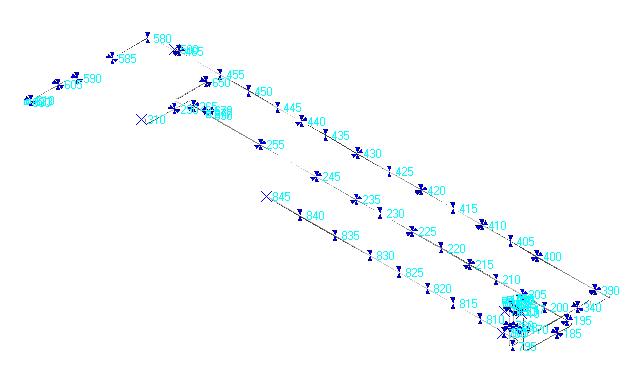
Qualifying ANSI B31.1 lines as seismic II/I:
Occasionally in nuclear power plants, the original design basis classifies a piping system as not related to nuclear safety. These lines arenormally designed to the requirements of ANSI B31.1. In most cases these lines are not required to resist seismic loads, or the seismic loading are greatly reduced. Due to design changes or configurations that are identified after the original design basis is established, it is determined that some of these ANSI lines can fail and impact safety related equipment. Because the lines are not originally designed to the strict ASME seismic requirements, qualifying them to the more stringent requirements is often difficult and can require the addition of supports.
In this project, Archon reviewed a system that, if it failed, could cause an uncontrolled drain down that could affect safety related equipment. The system was modeled in our pipes stress analysis software. The additional seismic loading was input using the required response spectra and the piping was analyzed to the ASME III requirements rather than the ANSI requirements. During the modeling process each support was reviewed to determine if it could restrain uplift or if it used U-bolts, which could restrain lateral loads. Some supports were removed from the model if they could not restrain uplift. After performing various runs to establish a realistic response of the system to a seismic event, it was determined that the stresses and supports on the system were adequate to prevent failure.
By performing this analysis we provided the client with assurance that the system would not impact safety related equipment during a seismic event, without performing any costly modifications.